What Is a Carbon Commutator Used For? In a brushed DC motor, a Carbon Commutator helps transfer electrical current between the stationary circuit and the rotating armature. Its segmented contact surface works with carbon brushes as the rotor turns. This switching keeps the magnetic pull on the armature moving in the right direction, helping the motor continue to spin. In some designs, carbon or graphite forms part of the commutating surface; materials and construction vary by application.
The detail is small, but its job is not. Picture a brush sliding over dark segments inside a motor housing. It must maintain contact while the rotor spins, without excessive sparking or heat. A worn surface can bring rough running, reduced output, or faster brush wear. Inspection matters.
Electrical-machinery author Stephen J. Chapman provides a useful technical foundation for understanding this process. The following is an editorial paraphrase, not a verified verbatim quotation: “The commutator switches armature connections as the rotor turns, sustaining torque.” That distinction matters. A commutator does not create energy; it helps manage current in a rotating machine. Nor does every motor use one. Brushless motors use different switching systems. Carbon components can also wear unevenly, and real-world performance depends on load, alignment, material, and maintenance. The explanation is simple. The engineering is less so. A practical guide should describe both the function and its limits, rather than treating every Carbon Commutator as identical.
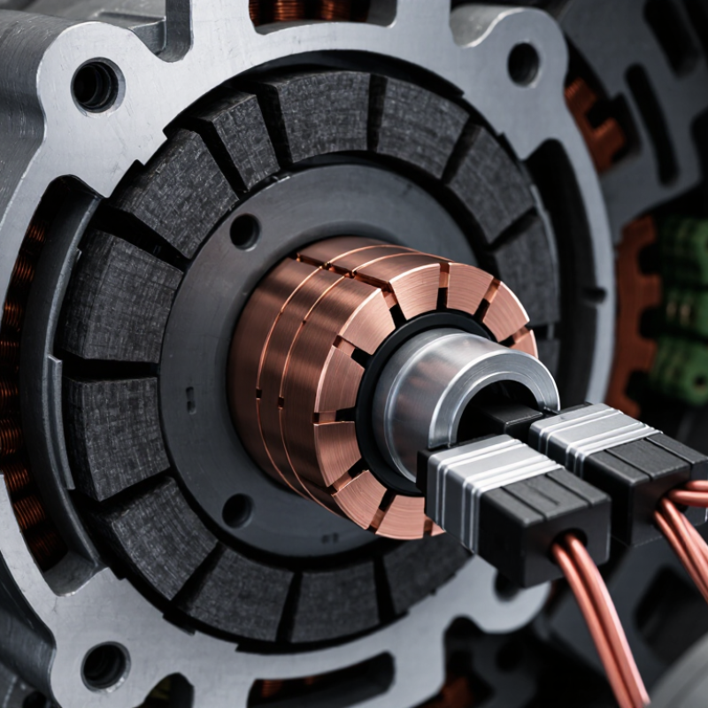
A carbon commutator is a rotating electrical contact assembly used in certain motors and generators. It connects the spinning armature windings with stationary carbon brushes, allowing current to pass while the rotor turns. Its surface is divided into conductive sections, so the electrical connection changes as the armature moves. That switching helps maintain torque in a direct-current motor.
The term can be confusing. A carbon commutator is not the same as a carbon brush, which presses against the commutator and carries current across the moving contact. Some commutators use carbon or graphite-based materials, while many conventional designs use copper segments. The material and construction depend on the machine’s current, speed, and operating conditions.
In practical use, the commutator must stay clean, smooth, and properly aligned. A dark ring of dust near the brush area may be normal wear, but heavy deposits, uneven grooves, or persistent sparking deserve inspection. Small details matter. Carbon-based surfaces can offer useful contact properties in particular applications, but they are not automatically better than copper. I would check the equipment specifications before identifying a part by appearance alone.
A carbon commutator transfers current between stationary wiring and a rotating armature, usually through carbon brushes that press against its copper segments. As the rotor turns, each brush slides across the commutator surface. The segments switch the armature’s electrical connections at the right moment, helping a DC motor maintain torque in one direction. In a generator, the commutator helps deliver current from the rotating coil to the external circuit. The contact is small, but it handles repeated electrical and mechanical stress.
Carbon is used because it conducts electricity while offering relatively low friction and gradual wear. That wear is intentional: brushes act as replaceable contacts, protecting the commutator from faster damage. The U.S. Department of Energy’s Improving Motor and Drive System Performance sourcebook reports that motor-driven systems account for about 64% of electricity use in the U.S. industrial sector. This figure covers many motor types, not just commutator machines, but it shows why reliable current transfer matters in industrial equipment.
Tips: Check brush length, spring pressure, and commutator cleanliness during maintenance. A dark, uneven track or heavy sparking may indicate poor contact, incorrect alignment, or excessive load. Don’t assume every spark means failure; operating conditions matter, and inspection should confirm the cause.
In a brushed DC motor, the commutator and carbon brushes work as a sliding electrical switch. The commutator is usually made of copper segments, rather than carbon. Carbon brushes press against those segments as the rotor turns, carrying current into the windings. As each coil passes the magnetic poles, the commutator reverses its current direction. That reversal keeps the rotor turning in the same direction. In a generator, the process works in reverse: the rotating windings produce current, and the commutator helps deliver it through the brushes as direct current. Small sparks and a faint brush hiss can occur during operation, but heavy sparking may point to wear, poor contact, or a damaged commutator.
The details matter. Brush pressure, surface condition, and alignment all affect contact and heat. Too much pressure increases friction; too little can cause intermittent current. The distinction between brush and commutator is easy to overlook, and it can lead to misdiagnosis during inspection. The International Energy Agency’s 2011 report, Energy-Efficiency Policy Opportunities for Electric Motor-Driven Systems, estimates that motor-driven systems use 43–46% of global electricity. The U.S. Department of Energy’s 2014 sourcebook, Improving Motor and Drive System Performance, reports that motor systems account for about 70% of industrial electricity use in the United States. These figures describe motor systems broadly, not commutator-equipped machines alone. Carbon brushes also wear by design, so technicians check brush length, spring pressure, and commutator grooves during maintenance.
A carbon brush presses against the rotating copper commutator, carrying current between the stationary circuit and the motor’s or generator’s rotating coil. In a DC generator, the commutator reverses the coil’s connection every half-turn, making the external voltage unidirectional.
Idealized single-coil model: voltage is normalized to its peak value and plotted against rotor angle. The commutator makes the external output one-directional; actual machines may have smoother output due to multiple coils and can show ripple under load.
Carbon commutator assemblies are found in brushed DC motors, where carbon brushes press against rotating copper segments to carry current. You’ll find them in cordless drills, mixers, vacuum cleaners, small pumps, and vehicle components such as window lifts and seat adjusters. The brush-and-commutator contact lets a motor change current direction as it spins. It also creates friction, heat, and gradual wear. A small part. But it needs careful matching to motor speed, current, and spring pressure.
Industrial equipment is another common setting, including conveyors, hoists, and older DC drive systems. The International Energy Agency’s 2011 report, Energy-Efficiency Policy Opportunities for Electric Motor Systems, estimated that motor systems used about 45% of global electricity. That figure covers motors broadly, not carbon-commutator machines alone; many modern motors use different designs. In service, technicians check brush length, dust buildup, commutator surface condition, and sparking. A gritty black residue near a motor may be normal brush wear, but heavy deposits or uneven scoring can signal a problem. There is no universal service interval. Actual wear depends on load, ventilation, and operating hours, so inspection records are more useful than guesswork.
What Is a Carbon Commutator Used For?
What Affects Their Wear and Performance
In a DC motor, carbon brushes press against the copper commutator to transfer current while the rotor turns. Their contact must stay steady, but it is never perfectly smooth. Brush wear depends on current density, rotational speed, spring pressure, alignment, and the thin surface film that develops during operation. Too much pressure can increase friction and heat. Too little can cause sparking and uneven contact. Small changes matter.
Humidity and contamination matter, too. Very dry air can disrupt the protective film; oil or dust can create a rough, unstable contact surface. The U.S. Department of Energy’s 2002 U.S. Industrial Electric Motor Systems Market Opportunities Assessment estimated that motor systems used about 68% of U.S. manufacturing electricity. That figure is not a brush-wear measurement, but it shows why motor reliability deserves attention. During inspection, look for uneven brush lengths, chipped edges, dark patches, and copper discoloration. Check that brushes move freely in their holders. A clean commutator is not automatically a healthy one. Readings and visual checks can disagree, so record wear over time and compare brushes under similar operating conditions.
| Topic | Purpose or factor | Effect on operation and wear | What to check |
|---|---|---|---|
| Current transfer | A commutator provides a sliding electrical connection between stationary brushes and the rotating armature in a brushed machine. | A stable contact helps maintain electrical continuity as the armature turns. | Look for uneven contact, excessive sparking, or interruptions in operation. |
| Current reversal | In a brushed DC motor, the commutator switches the connection to armature coils so their current reverses at the appropriate point in rotation. | Correct commutation supports continuous torque. Poor commutation can cause sparking, heating, and accelerated wear. | Check for persistent or unusually heavy sparking, especially under normal load. |
| Commutator material and design | Many commutators use copper segments separated by insulation; carbon or graphite commutator designs are used in certain machine applications. | Material, segment construction, and the intended brush type affect electrical contact, friction, and operating limits. | Use the machine maker’s specified replacement parts and service guidance. |
| Electrical load | Current level and current density at the brush-contact area influence heating and electrical stress. | Excessive load can increase temperature and arcing, contributing to surface damage and faster brush or commutator wear. | Compare operating load with the machine’s rated limits; investigate repeated overloads. |
| Rotational speed | Surface speed affects sliding contact, friction, and the time available for current switching. | Operation outside the design speed range can increase heat, vibration, sparking, or contact instability. | Confirm that the machine is operating within its specified speed range. |
| Brush pressure and alignment | Brush pressure must be appropriate, and brushes must sit squarely on the contact surface. | Too little pressure can cause intermittent contact and sparking; too much pressure can increase friction and wear. | Inspect brush seating, spring condition, and contact pattern according to service instructions. |
| Dust and contamination | Conductive dust, oil, moisture, and debris can affect the brush-contact surface. | Contamination may cause tracking, uneven contact, increased friction, or electrical leakage. | Keep the assembly clean and dry using approved maintenance methods; do not use unapproved lubricants. |
| Temperature and ventilation | High ambient temperature, restricted airflow, or excessive electrical and frictional heating raises operating temperature. | Overheating can damage insulating parts and accelerate wear or surface deterioration. | Check ventilation openings, cooling paths, and signs of discoloration or heat damage. |
| Vibration and runout | Mechanical vibration, shaft misalignment, or an uneven rotating surface can disturb brush contact. | Unsteady contact can produce localized wear, noise, sparking, and reduced service life. | Inspect for vibration, abnormal noise, loose parts, and uneven wear; measure runout when required. |
| Wear monitoring | Brush length, contact-surface condition, and the amount of sparking provide useful maintenance clues. | Severe grooving, burning, chipped surfaces, or brushes worn below their service limit can impair performance. | Inspect at the intervals specified for the machine and replace worn parts with the correct type. |
It is part of a rotating electrical contact assembly. It connects moving armature windings with stationary carbon brushes.
No. The brush presses against the commutator and carries current across the moving contact. Easy to mix up.
No. Many conventional commutators use copper segments. Materials depend on the motor’s current, speed, and operating conditions.
It changes current direction in the armature coils as the rotor moves. This helps keep the rotor turning in one direction.
Rotating windings produce current, and the commutator helps deliver it through the brushes as direct current.
Common examples include drills, mixers, vacuum cleaners, small pumps, and vehicle window or seat mechanisms.
A faint hiss, small sparks, or some dark dust may occur during normal wear. Heavy sparking or thick deposits need inspection.
They check brush length, spring pressure, alignment, dust, and commutator grooves. I would not judge condition by color alone.
There is no universal interval. Load, ventilation, and operating hours affect wear, so inspection records are more useful than guesswork.
A Carbon Commutator is a component that helps transfer electrical current between stationary and rotating parts of a machine. It typically works with carbon brushes, which maintain contact with the commutator as it turns. This connection allows current to flow while the rotor moves, supporting the operation of certain electric motors and generators.
In motors, a commutator can help direct current through the windings in a way that keeps rotation going; in generators, it helps collect and deliver current produced by the rotating parts. Carbon commutators are commonly found in equipment that uses brushed electrical machines. Their performance and service life depend on factors such as electrical load, rotational speed, contact pressure, heat, dust, and the condition of the brushes and commutator surface. Regular inspection can help identify wear, poor contact, or buildup that may affect reliable operation.